This is a cable driven drawing machine I constructed for the Telus Spark Science Centre in Calgary, Alberta.
Each of the four stepper motors is connected to a pulley and string. By winding in or letting out string on each corner the computer can position the draw head anywhere in three dimensional space, or at least within its work envelope of roughly 590x590x220mm.
The machine is controlled with LinuxCNC using a custom kinematics module and python script written by Kevin Loney. Its input files are standard g-code, the same format used for controlling a CNC mill, all the weird coordinate transformation math is handled by the kinematics wrapper.
More construction info and photos after the video,
By far the hardest thing on this build was getting the machine to to home fully automatically. For those new to motion control, I am using stepper motors, these are open loop which means that I can move them incrementally, but I have no idea where they actually are. To determine their current state, I have to move them to a known position, and call that home. This is fairly easy on a traditional CNC machine where each axis is independent and on guides, but quite painful when all four are tied together and made of string.
Many ideas
were floated to solve this, from IR range finders, to vision based systems with openCV
and a webcam. Finally for reliability I settled on simple switches.
From here though, there are two main problems, first, how do you trip a switch with a length of string, and second how do you keep everything taught and tangle free when you haven't got a clue where the drawhead is starting from.
The switches were the easy(er) part, the first attempt used a magnetic reed switch mounted over the fairleads (cable guides), and neodynium ring magnets mounted to the draw head. Once the magnets got close to the switch it would trip and tada! That was the theory at least, in practice they would fail to trip half the time, the magnets would stick to any ferrous metals in a 6 inch radius, and that was just the start of the problems. I got around some of the issues by using larger magnets, and brass screws, but it was really unworkable.
The final solution was to build custom rocker switches around the fairleads. They were spring loaded so that as the head was drawn into them, they would fold back and trip a small lever switch. They still had to be strong enough to keep the cable in the same position and they had to be rigid enough to not accidentally trip under normal load. Good times.
Now, to get the drawhead to trip the switch I have to have slack from the opposite side. The first thing I tried was to just spool out cable on one motor as I spooled in on the other. For a two cable machine this technique works great, once you get two more cords in the mix, and a lack of space to use gravity to keep things taught, a lot of tangles result. The solution was a bit of a hack, but one I am rather proud of. Stepper motors have no direct mechanical connection between the shaft and the body of the motor (well, other than the bearings), its the magnetic field in the coils that causes the shaft to turn. This means that stepper motors can slip without damage if the force on the shaft exceeds the holding torque of the coils. Further, the stepper motor driver I am using allows the current going into the motor to be adjusted with a resistor which then adjusts the holding torque. Yup, that's right, the motors have a tug of war. One is stronger than the others so it just reels it in with some enthusiasm, everything stays taught and you are off to the races.
This video shows the switches getting hit, I need to upload another video showing the unholy chunking and shaking that happens during the tug of war phase.
The construction of this machine was a mixture of hand machining, carpentry and a bit of laser cutting for the towers and overwrap guides. The head is replaceable, for the early tests I had a larger head that could mount a pen and do some fairly accurate drawings, only issue was that in a more resistive material like sand it tended to flop around a lot.
Motion test of my new draw bot. I have made my own DC servos by using a gear motor and a hall effect absolute angular position sensor. So now I can send a position over serial, and the robot will attempt to move there from wherever it is. I am using a PID loop to achieve this but still need to do some tweaking as you can see from the oscillations. Mostly this is due to the inertia of the arm being radically different depending on the extension.
I have been enjoying building drawbots of late. I find that they are a great way to learn about motion control systems, robotics, machining, and programing. Plus you know, robots that will do my bidding, how can you go wrong.
My next project is going to be a scaled up version of my pen plotter, this time capable of drawing on a sidewalk. Now because I don't want a 6' linear slide sticking out the front of my contraption, I am going to instead use a series of levers to get an approximate straight line that stays parallel to the ground. Here is an animation:
.
This linkage was designed in Linkage Mechanism Designer and Simulator an AWESOME free bit of software by David Rector. It is a wonderful program for working out linkages, and a massive improvement on my traditional cardboard and pins method.
To give you an idea of scale, the plan is to build this so that it will reach out about 6' when extended, giving me a drawing area of about 7'x4'
The construction is going to be fun, I am using 1"x1" alumium tube with 1/8" walls (Yup, despite the fact that I am in Canada a lot of stock is still sold in imperial measurements, its all arbitrary anyway really). Rather than just drilling a hole through the aluminum and bolting it I felt the need to go fancy and use sintered bronze and steel bushings press fit into the tubes. This reduces friction and makes it a lot more durable.
It took me a bit to work out how to get an accurate hole for the press fit, it has to be done to about 1/1000th of an inch tolerance (oh yeah, my milling machine is imperial as well). So if someone else is in the same boat here is how its done:
First drill a hole as close the final diameter as you can, unless you are like me and need an almost 3/4 inch hole and only have a 1/2 inch drillbit.
Next zero a set of digital calipers on the part you want to fit into the hole and then measure the hole, this will tell you how much material you have to remove.
The tool I am using to enlarge the hole is called a boring head, its basically a bit holder for boring bars that has a dovetail slide and a lead screw. By turning the lead screw you can offset the position of the boring bar within the hole. It has a graduated dial but its worthwhile to note whether the dial is set up to measure change in diameter or radius. In mine, its the later so all movements get doubled. ie. 10 thou on the dial removes 20 thou off the diameter.
Only use this tool on a milling machine, drill presses don't have strong enough bearings to hold up to the offset and out of balance cutting forces this tool creates. Unless that is, you like excitement.
Take a bit of metal off at a time until you get to your desired diameter, I was actually shooting for about 3 thou of interference on the fit, but forgot to account for the spring-back of the boring bar. It flexes ever so slightly under cutting loads so you have to do a few passes to make sure its the final size, I didn't do this on my penultimate pass so it caused me to overcut the final pass. Fortunately this is a test piece, and learning is fun.
Now if it was actually cut properly I would have had to use a press to put the bearing in, lets pretend anyway. This is a 2 ton manual rack arbor press.
Final step is to cross drill a steel pin. V-blocks greatly simplify this process.
Here is the joint assembled with cotter pins.
And a view down the end.You can see the bronze bushing on the right and the steel bushings on the left. The steel bushings are flanged so that the two bars don't contact over their entire length.
Do you know what is the best thing about having a drawing machine? Once you get bored of what it prints you can simply write a new program to make it do something different.
Like SVG output:
Or recursive fractal trees, randomized each time so it never draws the same thing twice:
So I've built my first CNC bot, a drawing machine. Because that wasn't quite difficult enough on its own I decided to make one that uses polar coordinates. That is, one with an arm that can spin on a base, and move in and out relative to the centre. It gives you a very large drawing surface with a minimum of moving parts compared to a standard x,y Cartesian plotter. I was inspired by similar projects online, like the eggbot and the polargraph which uses a dual polar coordinates system; mines a single.
The general setup is a pair of nema-17 motors, being run by dSpin motor drivers. Nice chips, you can set them up with your parameters in terms of what acceleration and max speed you want as well as the micro-step mode and after that you just tell it to move forward X steps. It handles all the movement profile and it also has a full suite of protection systems built in. They communicate over SPI to an Arduino, which is then hooked up over USB/serial to a laptop running Processing. Yup its definitely convoluted but oddly functional. The laptop is used to convert and process an image, and send the required movements line by line to the Arduino which just relays it to the dSpin boards. I will be posting code a bit later once I make it slightly more friendly than the convoluted mess it is in now. You can see the set up to the left.
One important note, if you use a solenoid for the pen lifter you need a really good diode to drain the current when you depower it otherwise the back EMF does bad things. I blew up the pull up resistor on two output pins on my arduino before I figured out that my 1N4004 diode just wasn't working. In the interests of overkill I added an optical isolator and a schottky diode rated at 600v and 4amps with a 4ns response time. Over-specced, but only $1.20 delivered.
Here are some videos, first the movement test:
First drawing:
After that first test, and showing the project off at my first makers faire, I rewrote the code so it automatically converts the coordinates from polar to cartesian so it gets rid of the distortion. I still get a few rounding errors as you can tell by the slightly wavy baseline, it also now skips over white space and goes a whole heck of a lot faster.
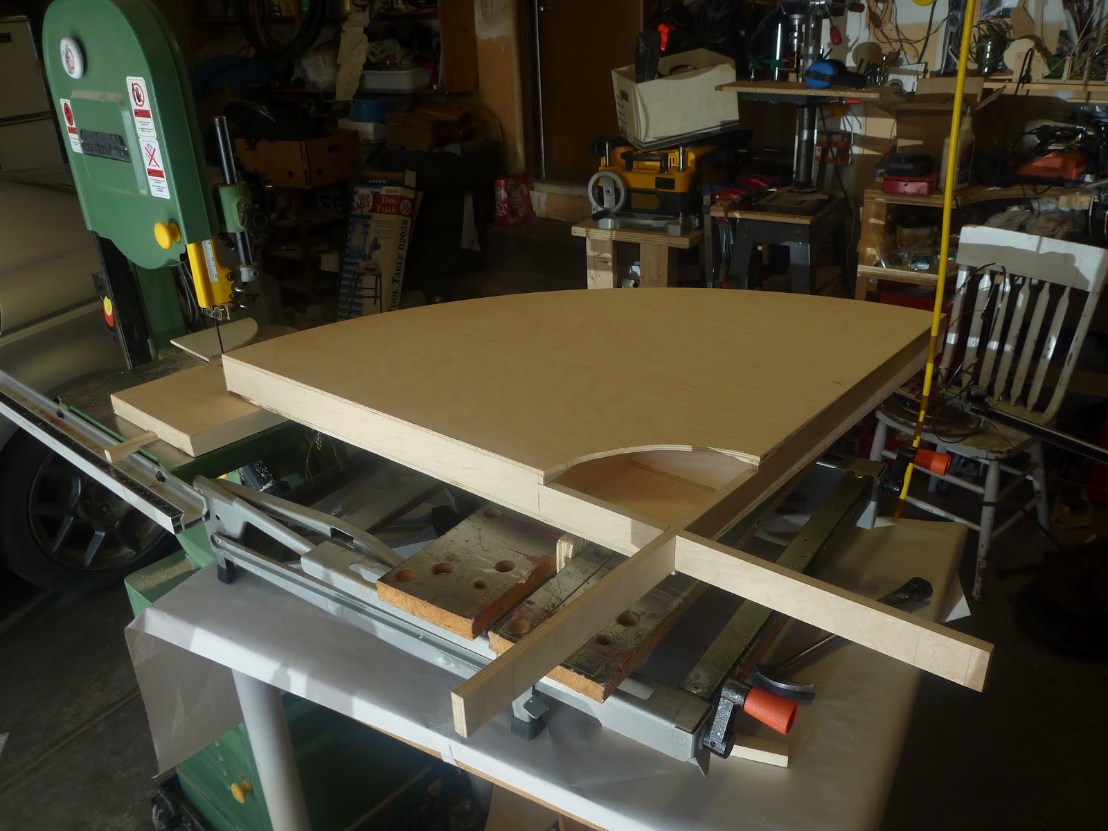
As for the build. I will start with the easy part, carpentry. Because my pen holder design has limited travel I needed a fairly flat and true surface or else I would end up with gaps and extra lines in my drawing. I decided to go with a torsion box design build out of a bunch of scrap 1/4" baltic birch I had in my shop. Its slightly overkill.
Once I got it glued up and assembled using every clamp in the shop, plus an anvil, blower, forge, and anything else heavy on top. I needed to cut it into an arc. So, one nail, a piece of wood, a workmate and a bit of creative stacking I got it set up next to my bandsaw.
I should note around this point that I wasn't really working from plans, or a design, my process for prototypes like this is more.. I don't know.. industrial jazz? Winging it while machining? Something like that. The goal was to get it working and then worry about making it pretty, which I will get to eventually.
You can see the rotation axis in the image on the right. General plan is that I have a large lazy susan bearing attached to the base. Also attached and stationary is a 52 tooth gear off a 1970's bike. The gear and chain are basically stationary while the motor runs around on the inside of the chain. I built my own jackshaft assembly that lets me hook up the 11 toothed sprocket off a rear derailer to a 60 tooth timing belt pulley, this is in turn hooked up to a belt and an 18 tooth pulley on the motor. Simple right? The reason for the arrangement was to gear down the motor and get a bit more resolution on the arm. Trade off is that I have about an inch of backlash. I need to build in an idler tensioner so I can tighten the chain without it binding and that should cut it down some. If that doesn't I will just measure the error and write it into the code.
That is the process for the jackshaft build. I couldn't fit the bearing holder plates on my small lathe so I cut the bearing seats using a rotary table on my mill. You need to get the holes about 4 thousandths of an inch undersized for the bearings to press fit in securely. The shaft is steel, and from personal experience the set screws and flats are mandatory, I spent about an hour debugging my code till I figured out that the timing pulley was slipping. The holder for the 11 tooth sprocket is pretty easy and straight forward, a piece of aluminum bored for the shaft diameter and then a seat was cut slightly over 1cm (the size of the inner bore of the sprocket) the whole shebang was press fit together and a hole was drilled and tapped for the set screw. Come to think of it, its amazing on projects like this how the definition of easy changes over time.
The linear movement is shown to the right. I cheated and used a commercial linear slide due to its higher strength, accuracy, and durability compared to anything I could fabricate at home. Also, it was only 40 bucks. I couldn't make it for cheaper. To drive it I put a jackshaft at the end with an idler pulley, and mounted the motor behind the slide. I ended up building a small clamp to hold onto the belt using friction. Its pretty bodgy but it works.
The photos above show the construction of the most important part of the build, the pen holder. Made out of scraps on the lathe and mill, for a prototype I am pretty happy with it. Actuation is achieved with a 12v solenoid coil and return spring. This is version two. Version one was an attempt to move the pen linearly, straight up and down. It jammed a lot. Rigging the pen on a pivot like this is way more rigid and reliable. I am already starting to design version three. The problem with this one is that its hard to get set up correctly. The pen has to be adjusted till its in the exact right position, too low and it will dig into the paper, too high and it wont write correctly. Adjustments are fortunately easy, one set screw holds the pen in place inside the tube. This design allows the machine to hold everything from a pencil to a fat sharpie. The mount point is also rigged so that no matter what size pen it always centres to the same point relative to the linear slide. Oh, one other important modification, I packed foam between the solenoid driving rod and the pen pivot, this allows the system to have a bit of give to account for variations in the surface. My next plan is to set it up so the solenoid lifts the pen, this will mean I have to add a parking brake so the pen doesn't constantly sit on the paper when its depowered, but should make the whole thing a little faster and allow me to set the pen tension with a spring rather than uneven coil pressure.
The image to the left gives you an idea on the resolution I am getting, the scale is in centimeters. This is with me running the motors at 1/16 microstepping, the dSpin drivers let me go up to 1/128th so its possible to get really really fine resolution out of it.
Oh, and as for suppliers (I have no connection to any of these companies but I am posting links so it might help you chase down some of the more obscure parts).
Sparkfun for the dspin driver breakout boards
Solarbotics motors electronics etc - also carries the sparkfun dspin breakout boards, based in Calgary.
Misumi - Motion control components so all the pulleys, belts, linear slides, bearings etc.
Lee valley carries the big lazy susan bearings.
Digikey canda - the old standby, now has a Canadian warehouse. Their catalog and inventory is the most overwhelming thing I have ever seen but they carry everything. I got most of my electronic components, and a big 12v 6a power transformer from them.
This is the blog I use to post all the various incomplete projects I am working on, some art related some not. For more of my work you can look at my portfolio.
Boats Canoe ( still need to name her) - 11' 15lb skin on frame Canoe Sage - a 16.5' skin on frame Aleut Baidarka sea kayak Carina - a 14' skin on frame Aleut Baidarka kayak
David Bynoe is a multidisciplinary kinetic sculptor working in Calgary, Alberta.
David graduated from the Alberta College of Art and Design in 2006 with a Bachelors degree in Jewelery and Metals. Between 2008 and 2009 he worked as a Studio Workstudy at the Banff Centre for the Arts, assisting artists and facilitators in the wood, metal and ceramics shops. He is currently employed as a Graphic Designer and Photographer with Avison Young Real Estate.


 By far the hardest thing on this build was getting the machine to to home fully automatically. For those new to motion control, I am using stepper motors, these are open loop which means that I can move them incrementally, but I have no idea where they actually are. To determine their current state, I have to move them to a known position, and call that home. This is fairly easy on a traditional CNC machine where each axis is independent and on guides, but quite painful when all four are tied together and made of string.